Download Komatsu PW180-7EO Hydraulic Excavator Service & Repair Manual –

book store
Cleaning the intake manifold on a Komatsu PW180-7EO Hydraulic Excavator is a critical maintenance task that helps ensure optimal engine performance. click here for more details on the download manual…..


    komatsu pw180 tyre exc.annoying sound errors,due to brake oil pressure low thia video is showing the step by step way to repair the problem.

    Komatsu PW180-7 K for sale @ lamersmachinery.com Komatsu PW180-7 K for sale @ lamersmachinery.com Check out our website http://lamersmachinery.com Follow our Facebook …

Here’s a reverse order guide to performing this task:

### 7. **Reassemble Components:**
– Reinstall any components that were removed during the disassembly process, such as air intake hoses, electrical connectors, and other associated parts.
– Ensure all connections are secure and properly aligned.

### 6. **Reconnect the Battery:**
– Reconnect the negative terminal of the battery to restore power to the excavator.

### 5. **Test Run the Engine:**
– Start the engine and allow it to idle for a few minutes.
– Check for any unusual noises, leaks, or warning lights on the dashboard.
– Ensure that the engine runs smoothly and that there are no issues with the air intake.

### 4. **Rinse and Dry the Manifold:**
– Rinse the intake manifold with clean water to remove any remaining cleaning solution or debris.
– Allow the manifold to dry completely before reinstallation.

### 3. **Clean the Intake Manifold:**
– Use a suitable cleaning solution, such as a degreaser or solvent, to clean the surfaces of the intake manifold.
– Scrub the manifold with a brush to remove carbon deposits, dirt, and other contaminants.
– Rinse thoroughly to remove any cleaning agents.

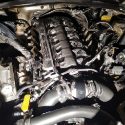
### 2. **Remove the Intake Manifold:**
– Disconnect any hoses or cables attached to the intake manifold.
– Unbolt the manifold from the engine block, taking care to keep track of any gaskets or seals that may need replacement.

### 1. **Prepare the Workspace:**
– Ensure you have all necessary tools, safety gear, and cleaning supplies ready.
– Park the excavator on a flat, stable surface and engage the parking brake.
– Disconnect the battery to prevent any electrical issues.

### Additional Notes:
– Always consult the Komatsu PW180-7EO service manual for specific instructions and torque specifications.
– Properly dispose of any cleaning materials and worn gaskets as per local regulations.
– If you’re unsure about any step, consider consulting a professional mechanic or technician.

By following these steps in reverse order, you can effectively clean the intake manifold of the Komatsu PW180-7EO Hydraulic Excavator while ensuring that the process is organized
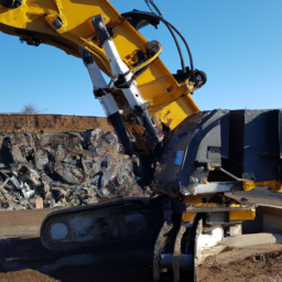
download Komatsu PW180 7EO Hydraulic Excavator workshop manual and thorough.
A hydraulic clutch line is a crucial component in a vehicle’s hydraulic clutch system, which is responsible for engaging and disengaging the clutch mechanism in a manual transmission. This line is typically made from high-pressure-resistant materials, such as rubber or reinforced plastic, designed to withstand the hydraulic pressure generated during clutch operation.

The hydraulic clutch system operates on the principle of hydraulic fluid under pressure, which allows for smoother and more efficient clutch engagement compared to traditional mechanical linkages. When the driver depresses the clutch pedal, the pedal pushes a master cylinder that forces hydraulic fluid through the hydraulic clutch line to the slave cylinder located near the clutch assembly. This action creates the necessary pressure to disengage the clutch, enabling the driver to shift gears smoothly.

One of the primary advantages of a hydraulic clutch line is its ability to provide a more consistent and responsive clutch feel, which enhances drivability. Additionally, it reduces the physical effort required by the driver to operate the clutch, making it more user-friendly, especially in stop-and-go traffic.

However, hydraulic clutch lines can be susceptible to wear, leaks, and damage from extreme temperatures or mechanical stress, which can lead to clutch failure or decreased performance. Regular inspection and maintenance of the hydraulic system, including the clutch line, are essential to ensure optimal functionality and longevity of the vehicle’s transmission system.

Download Mazda MX-3 MX3 Service Repair Workshop Manual 1991-1998 –

get
Repairing the drivetrain on a Mazda MX-3 involves several steps and a variety of tools. click here for more details on the download manual…..


    1992 Mazda MX-3 Precidia GS 1.8 V6 (Eunos/Presso/AZ-3) – Driver's Seat CDN AS TESTED $13500 BASE MSRP RETRO CAR REVIEW’S & ROAD TEST’S.

    1994 Mazda MX-3 Overheating Radiator Bleeding My Mazda keeps overheating after driving it for about 10 minutes. It happens when I’m slowing down or at idle usually with AC on …

Below is a detailed guide on the process, including the tools you will need:

### Tools Required

– **Socket Set**: A complete set including shallow and deep sockets in metric sizes (8mm to 19mm) for removing bolts from the drivetrain components.
– **Ratchet and Extensions**: For better reach and leverage when removing bolts in tight spaces.
– **Torque Wrench**: To ensure that all bolts are tightened to the manufacturer’s specifications.
– **Wrenches**: A set of open-end and box-end wrenches for various sizes of nuts and bolts.
– **Pliers**: Needle-nose and standard pliers for gripping and pulling components.
– **Screwdrivers**: Flathead and Phillips screwdrivers for removing clips and covers.
– **Pry Bar**: For separating stuck components, particularly when removing the transmission or differential.
– **Jack and Jack Stands**: To safely lift and support the vehicle while you work underneath it.
– **Transmission Jack**: Optional but helpful for supporting the transmission during removal and installation.
– **Fluid Drain Pan**: To catch any fluids that may leak during the repair process.
– **Shop Manual or Repair Guide**: A reference for torque specifications, assembly diagrams, and troubleshooting tips.

### Drivetrain Repair Steps

– **Prepare the Workspace**: Ensure you have a clean, organized workspace with sufficient lighting. Gather all tools and equipment before starting the repair.

– **Lift the Vehicle**: Use the jack to lift the rear of the Mazda MX-3 and secure it on jack stands to prevent accidental falls while you work underneath the car.

– **Remove the Wheels**: Take off the rear wheels to access the drivetrain components, including the differential and drive axles.

– **Drain Fluids**: Use the fluid drain pan to catch any remaining transmission fluid or differential oil. Locate the drain plugs and remove them carefully.

– **Inspect the Drivetrain**: Before proceeding, visually inspect the driveshaft, CV joints, and differential for any signs of wear, leaks, or damage.

– **Remove the Driveshaft**:
– Unbolt the driveshaft from the differential using the socket set.
slide the driveshaft out of the transmission. You may need to use a pry bar gently to free it if it’s stuck.

– **Remove the Differential**:
– If necessary, unbolt the rear differential from its mounting points.
– Disconnect any wiring or sensor connections attached to the differential.
– Carefully lower the differential using the transmission jack, ensuring it is balanced to prevent damage.

– **Inspect Components**: Check the CV joints, bearings, and seals for damage. Look for signs of wear such as cracks or excessive play.

– **Replace Damaged Parts**:
– If any components are worn or damaged, replace them with new parts.
– Ensure that you use OEM parts or high-quality aftermarket parts for longevity.

– **Reassemble the Drivetrain**:
reinstall the differential, making sure to align it correctly with the driveshaftdownload Mazda MX 3 MX3 workshop manual and securing it with bolts to the manufacturer’s torque specifications.
– Reattach the driveshaft to the transmission and differential, ensuring a snug fit and secure fastening.

– **Refill Fluids**:
– Refill the differential and transmission with the appropriate fluids according to the specifications in the shop manual.
– Check for leaks around the seals and bolts after refilling.

– **Reinstall Wheels and Lower the Vehicle**:
– Put the wheels back on and lower the vehicle from the jack stands.
– Tighten the lug nuts to the manufacturer’s specifications.

– **Test Drive**:
– Take the vehicle for a short test drive to ensure that everything is functioning correctly.
– Listen for unusual noises or vibrations that could indicate a problem with the drivetrain.

– **Final Inspection**: After the test drive, recheck all fluid levels and inspect for leaks or any loose bolts.

### Safety Precautions

– Always wear safety gear such as Gloves and goggles when working on vehicles.
– Ensure the vehicle is securely supported by jack stands before working underneath it.
– Be cautious of hot components and fluids that may have been used in the vehicle.

Following these steps will help you successfully repair the drivetrain on a Mazda MX-3. Always refer to the vehicle’s service manual for specific details and specifications related to your model year.
The neutral safety switch is a crucial component in modern automatic transmission vehicles, designed primarily to enhance safety during vehicle operation. Its primary function is to prevent the engine from starting unless the transmission is in the “neutral” or “park” position. This feature is essential as it helps to avoid accidental vehicle movement, which can lead to accidents or injuries.

Typically located on the transmission or near the gear selector, the neutral safety switch interacts with the vehicle’s electrical system. When the ignition is turned on, the switch completes a circuit only when the gear shift is in the correct position. If the switch is faulty or misaligned, the engine may not start, or the vehicle may start in an inappropriate gear, posing a significant safety risk.

The importance of the neutral safety switch is underscored by its role in ensuring that drivers can start their vehicles safely and without unexpected movement. In addition to its primary function, it may also serve additional roles, such as providing input for the reverse lights, indicating when the vehicle is in reverse gear. regular inspection and maintenance of the neutral safety switch are recommended to ensure optimal vehicle performance and safety, as neglecting this component can lead to starting issues or unsafe driving conditions.

Download 1974 Volkswagen Golf Mk1 3 Doors Download Service & Repair Manual –

repair manual
Adjusting the parking brake on a Volkswagen Golf Mk1 (3 doors) involves several steps to ensure proper functionality and safety. click here for more details on the download manual…..


    VW GOLF MK1.HOW TO MAKE CLUTCH PEDAL SOFTER.#hardclutch #golfmk1 #vwgolf #golfmk2 #vwcaddy #vwfox The GOLF MK1,Generally has a Harder Clutch Pedal., but if extremely hard, it could be due to negligence. Doing a few checks …

    PR353 WV Golf MK1 Door Seal You can find the WV Golf MK1 Door Seal right here parmegastore.com/products/pr353-vw-golf-mk1-door-seal?

Here’s a detailed guide on how to perform the adjustment:

– **Gather Necessary Tools:**
– **Jack and Jack Stands:** To lift the vehicle safely.
– **Wheel Chocks:** To prevent the vehicle from rolling.
– **Socket Set:** For removing the rear wheels.
– **Torque Wrench:** To ensure proper tightening of bolts.
– **Pliers:** For adjusting the parking brake cable if necessary.
– **Flathead Screwdriver:** For prying or adjusting components.
– **Ruler or Measuring Tape:** To measure brake lever travel.

– **Prepare the Vehicle:**
– Park the vehicle on a flat surface and engage the regular brake.
– Place wheel chocks behind the front wheels to prevent any movement.
– Loosen the lug nuts on the rear wheels (do Not remove them completely yet).

– **Lift the Vehicle:**
– Use the jack to lift the rear of the car. Secure it with jack stands for safety.
– Remove the rear wheels completely to access the brake components.

– **Inspect the Parking Brake System:**
– Locate the parking brake cable that runs from the handbrake lever to the rear brakes.
– Check for any wear, fraying, or damage on the cables and connections. Replace if necessary.
– Look at the brake shoes in the rear drums (if equipped) or the calipers (if disc brakes) to ensure they are in good condition.

– **Adjust the Brake Shoes (Drum Brakes):**
– If the Golf Mk1 has drum brakes, locate the access hole on the back of the drum.
– Use a flathead screwdriver to adjust the star wheel inside the drum. this will move the brake shoes closer to the drum.
– Turn the star wheel until you feel resistance when rotating the drum. Back it off slightly until the drum turns freely.

– **Adjust the Parking Brake Cable:**
– Locate the parking brake adjustment nut under the vehicle, typically near the rear axle.
– Use pliers to loosen the jam nut on the cable.
– Turn the adjustment nut to increase or decrease the tension on the cable. You want the cable to be taut but Not overly tight.
ensure there is a slight amount of free play in the parking brake lever (usually about 2-3 clicks).

– **Reassemble and Test:**
– Reinstall the rear wheels and tighten the lug nuts by hand.
– Lower the vehicle back to the ground using the jack and remove the jack sdownload Volkswagen Golf Mk1 3 Doors workshop manualtands.
– Tighten the lug nuts to the manufacturer’s specified torque using a torque wrench.
– Test the parking brake by pulling the lever. It should engage firmly within 5-7 clicks and hold the vehicle stationary.

– **Final Check:**
– Take the vehicle for a short test drive to ensure the parking brake holds properly when engaged.
– Re-check the adjustment if necessary, and ensure all tools are removed from the vehicle.

Following these steps carefully will help ensure your parking brake is functioning correctly and safely on your Volkswagen Golf Mk1.
A tachometer is a crucial instrument found in vehicles that measures and displays the engine’s rotational speed, typically expressed in revolutions per minute (RPM). this component is essential for both performance monitoring and engine management, providing drivers with real-time data about how fast the engine is operating. By displaying the RPM, the tachometer helps drivers understand the engine’s current workload and performance level, which is particularly important in manual transmission vehicles where shifting gears at the right RPM can optimize efficiency and power.

The tachometer operates by receiving signals from the engine’s ignition system or from a sensor that detects the crankshaft’s rotation. In modern vehicles, digital tachometers are common, providing a clear and precise readout, often integrated into a vehicle’s dashboard along with other gauges. Traditional analog tachometers feature a needle that moves across a dial, providing a more tactile reading of the engine speed.

Drivers use the tachometer to avoid over-revving the engine, which can cause damage and lead to decreased performance. In performance driving situations, such as racing, the tachometer becomes even more critical as it assists in maximizing acceleration and ensuring optimal gear shifts. Furthermore, the tachometer can also play a role in fuel efficiency; by maintaining the engine within a specific RPM range, drivers can achieve better mileage and reduce emissions. Overall, the tachometer is an indispensable tool that enhances both vehicle performance and driver awareness.

Download VAUXHALL OPEL CORSAService & Repair Manual 2000-2004 –

book shop
Replacing the anti-roll bar (also known as a stabilizer bar) on a Vauxhall Opel Corsa involves several steps and requires a good understanding of automotive mechanics. click here for more details on the download manual…..


    How to change a front shock strut on OPEL CORSA D [TUTORIAL AUTODOC] How to change a front shock strut on OPEL CORSA D 4 (L08, L68) 1.3 Hatchback 2006–2014 [TUTORIAL AUTODOC] …

    Changing front Brake Pads and Discs Vauxhall Corsa D Changing the brake pads and brake discs on the Vauxhall Opel Corsa D.

Below is a detailed guide on how to perform this replacement. Please ensure you have the necessary tools and safety equipment before you start.

### Tools and Equipment Needed:
1. **Safety Equipment:**
– Safety goggles
– Gloves
– Steel-toed boots

2. **Tools:**
– Jack and jack stands
– Wheel chocks
– Socket set (metric)
– Wrenches (metric)
– Torque wrench
– Pry bar
– Hammer
– Pliers
– Screwdrivers
– A bungee cord or rope (to support suspension components if needed)

3. **Replacement Parts:**
– New anti-roll bar (ensure it’s the correct part for your specific model)
– New anti-roll bar bushes (often included with the bar, but check)
– New end links (if applicable)

### Step-by-Step Replacement Process:

#### 1. Preparation:
– **Safety First:** Park your vehicle on a flat surface, engage the handbrake, and place wheel chocks behind the rear wheels to prevent movement.
– **Gather Tools:** Have all your tools and replacement parts ready.

#### 2. Lift the Vehicle:
– **Loosen Lug Nuts:** Using a lug wrench, slightly loosen the lug nuts on the front wheels but do not remove them completely.
– **Jack Up the Vehicle:** Use a hydraulic jack to lift the front of the vehicle and place jack stands under the appropriate jacking points for added safety.
– **Remove Front Wheels:** Once the vehicle is secure, remove the lug nuts completely and take off the front wheels.

#### 3. Locate the Anti-Roll Bar:
– The anti-roll bar is a long metal bar that runs across the vehicle, connecting the left and right suspension components. It is typically mounted to the chassis with rubber bushings and may have end links connecting it to the lower control arms.

#### 4. remove the End Links:
– **Identify End Links:** These are the vertical connections between the anti-roll bar and suspension arms.
– **Disconnect End Links:** Use a wrench to remove the bolts securing the end links to the anti-roll bar and the suspension components. You may need to hold the end link with pliers to prevent it from spinning while you remove the nut.

#### 5. remove the Anti-Roll Bar from Mounts:
– **Locate Mounting Bolts:** Find the bolts that secure the anti-roll bar to the chassis. There will typically be two brackets with bolts on each side of the bar.
– **Remove Bolts:** Use a socket and ratchet to remove these bolts. If the bolts are rusted or stuck, you may need to apply penetrating oil and let it sit for a few minutes.
– **Remove the Anti-Roll Bar:** Once all bolts are removed, you can carefully slide the anti-roll bar out of its mounts. Be cautious of any wiring or components that might be in the way.

#### 6. Install the New Anti-Roll Bar:
– **Position the New Bar:** Align the new anti-roll bar in the same position as the old one. If it comes with new bushings, make sure to install them as well.
– **Secure the Bar:** Insert the anti-roll bar into the mountsdownload VAUXHALL OPEL CORSA workshop manual and hand-tighten the bolts. Make sure the bar is aligned properly.
– **Torque the Bolts:** Use a torque wrench to tighten the mounting bolts to the manufacturer’s specifications (check the service manual for the correct torque settings).

#### 7. Reattach End Links:
– **Install New End Links:** If you have new end links, install them at this time. Attach one end to the anti-roll bar and the other to the suspension arm.
– **Tighten End Link Bolts:** Ensure they are secured properly and torque them to the specified settings.

#### 8. Reinstall Wheels:
– **Replace Front Wheels:** Place the front wheels back on and hand-tighten the lug nuts.
– **Lower the Vehicle:** Carefully lower the vehicle back to the ground using the hydraulic jack. Once it’s on the ground, use a torque wrench to tighten the lug nuts to the specified torque setting.

#### 9. Final Checks:
– **Inspect the Installation:** Ensure that everything is properly secured and that there are no loose components.
– **Test Drive:** Take the vehicle for a test drive to ensure that the handling feels correct and that there are no unusual noises.

### Conclusion:
Replacing the anti-roll bar on a Vauxhall Opel Corsa is a manageable task for someone with Basic mechanical skills. Always refer to your vehicle’s service manual for specific torque settings and detailed diagrams. If you’re uncertain at any point, consider consulting a professional mechanic to assist with the replacement.
Wheel alignment refers to the adjustment of a vehicle’s suspension system, which connects the car to its wheels. Proper alignment ensures that the wheels are positioned correctly relative to each other and to the road, which is crucial for optimal vehicle performance. The primary parameters involved in wheel alignment include camber, caster, and toe angles.

Camber measures the tilt of the wheels in relation to the vertical axis. If the tops of the wheels lean outward, it’s called positive camber, while inward tilt is negative camber. Both extremes can lead to uneven tire wear and affect handling. Caster measures the angle of the steering axis, which can impact steering stability and returnability. Positive caster enhances straight-line stability, while negative caster can make a vehicle feel unstable.

Toe refers to the direction the tires point relative to the centerline of the vehicle. If the front of the tires is closer together than the rear, it is known as toe-in; if the rear is closer, it’s toe-out. Improper toe alignment can cause tires to wear unevenly and can affect the car’s responsiveness.

Regular wheel alignment checks are essential for maintaining tire life, improving fuel efficiency, and ensuring safe handling. Misalignment can result from various factors, such as hitting potholes or curbs, and may require professional adjustment to restore proper vehicle dynamics.

Download Ford Sierra Hatchback 1982-1993 Factory Service Manual –

book store
Repairing the stabilizer bar (also known as the anti-roll bar) on a Ford Sierra Hatchback may seem daunting if you have little mechanical experience, but I’ll guide you through the process step by step in simple terms. click here for more details on the download manual…..


    how to FIX a rust hole in a rocker panel (fast, low-cost method) Fixing a rust hole on the rocker panel can be expensive. I’ve done body work on cars for a lot of years, and have developed some …

    Ford Sierra Cosworth "Replacing Springs Allround,Shock Replacement Upfront"Hints n Tric… Hey there people Finally i got around to replacing the front shock that was giving me headache.One of the Bilstein shocks had a …

The stabilizer bar helps reduce body roll when the vehicle turns, so keeping it in good shape is important for handling and safety.

### Tools and Materials You Will Need:
1. **Tools:**
– Jack and jack stands (or ramps)
– Wrench set (or socket set)
– Screwdriver
– Pliers
– Torque wrench (optional but recommended)

2. **Materials:**
– New stabilizer bar links (if they are damaged)
– New bushings (if needed)
– Grease (if applicable)
– Cleaning cloths

### Step-by-Step Guide:

#### 1. Safety First
– **Park the Car:** Make sure your car is on a flat, level surface.
– **Engage the Parking Brake:** This keeps the car from moving while you work.
– **Wear Safety Gear:** consider wearing gloves and safety glasses.

#### 2. Lift the Car
– **Use a Jack:** Place the jack under the front or rear of the car (depending on which stabilizer bar you’re working on) and lift the vehicle.
– **Secure with Jack Stands:** Once the car is lifted, place jack stands under the vehicle to keep it stable and secure.

#### 3. Locate the Stabilizer Bar
– **Find the Bar:** The stabilizer bar runs across the width of the vehicle, typically near the front suspension. It’s a metal rod connected to the suspension on both sides.

#### 4. Inspect the Stabilizer Bar
– **Check for Damage:** Look for any bends, cracks, or excessive wear on the bar itself. Also, check the links (the parts connecting the bar to the suspension) and the bushings (the rubber parts that cushion the bar).

#### 5. Remove the Damaged Parts
– **Loosen Bolts:** Use your wrench or socket set to loosen and remove the bolts that hold the stabilizer bar links and bushings in place.
– **Take Out the Links:** If they’re damaged, pull the links off the stabilizer bar and the suspension. Note how they are connected for reinstallation.
– **Remove Bushings (if needed):** If the bushings are worn out, slide them off the stabilizer bar.

#### 6. Install New Parts
– **Attach New Bushings:** Slide new bushings onto the stabilizer bar in the same position as the old ones.
– **Connect New Links:** Attach the new stabilizer bar links to the bar and the suspension. Make sure they are positioned the same way as the ones you removed.
– **Tighten Bolts:** Use your wrench or socket to tighten the bolts securely. If you have a torque wrench, refer to the car’s manual for the correct torque specifications.

#### 7. Recheck Your Work
– **Ensure Everything is Tight:** Go over all the bolts and connections to make sure everything is secure.
– **Check for Movement:** Make sure the stabilizer bar can move freely without any obstruction.

#### 8. Lower the Car
– **Remove Jack Sdownload Ford Sierra Hatchback workshop manualtands:** Carefully lift the car slightly with the jack, remove the jack stands, and then lower the car back to the ground.

#### 9. Test Drive
– **Take It for a Spin:** After everything is reassembled, take the car for a short test drive to ensure everything feels right. Listen for any unusual noises, which could indicate that something isn’t installed correctly.

### Final Tips:
– **Check Your Work:** If you notice any issues after the repair or if you’re unsure about anything, it’s best to consult a professional mechanic.
– **Routine Maintenance:** Regularly check your stabilizer bar and links for wear, especially if you drive on rough roads.

With patience and care, you can successfully repair the stabilizer bar on your Ford Sierra Hatchback. Good luck!
A wheel cylinder is a crucial component in the drum brake system of a vehicle, primarily found in older cars and some light trucks. Its primary function is to facilitate the braking process by converting hydraulic pressure from the brake system into mechanical force that applies the brake shoes against the inside of the brake drum.

The wheel cylinder is essentially a cylindrical housing that contains two pistons. When the driver presses the brake pedal, hydraulic fluid from the master cylinder flows into the wheel cylinder. This fluid exerts pressure on the pistons, causing them to move outward. As the pistons move, they push the brake shoes against the drum, creating the necessary friction to slow down or stop the vehicle.

Made from durable materials to withstand High pressure and resist corrosion, wheel cylinders are typically designed to be compact and lightweight. However, they can be prone to wear and tear over time. Common issues include leaks due to worn seals or corrosion that can lead to reduced braking efficiency or complete brake failure if left unaddressed. Regular maintenance checks are essential to ensure that the wheel cylinders function properly, as they play a vital role in the overall safety and performance of the braking system. Properly functioning wheel cylinders are essential for effective stopping power and overall vehicle safety.

Download BMW 3 Series E36 Service Repair Workshop Manual 1991-199 –

sale
Repairing the suspension strut tower on a BMW E36 (produced from 1991 to 1999) can be a complex task, as it often involves addressing rust or structural damage to the body where the strut mounts. click here for more details on the download manual…..


    Top 5 Problems BMW 3 Series Sedan E46 4th Generation 1997-06 Shop for New Auto Parts at 1AAuto.com http://1aau.to/c/16/cu/window-regulator These are the top 5 problems with the 4th …

    RESTORING A BMW E36 BARNFIND IN 16 MINUTES! This description contains affiliate links for which I may be compensated* As an eBay Partner, I may be compensated if you make a …

Below are detailed steps and descriptions of components involved in the repair process. Please ensure you have proper safety gear and tools before proceeding.

### Tools and Materials Needed

1. **Tools**:
– Jack and jack stands
– Socket set (including deep sockets)
– Wrenches (metric sizes)
– Torque wrench
– Hammer
– Chisel
– Drill (with metal bits)
– Angle grinder or cutting tool
– Welding machine (MIG or TIG)
– Sandpaper or a wire brush
– Safety goggles and gloves
paint or rustproofing spray

2. **Materials**:
– Steel plate or metal repair panel (for patching)
– Welding wire (if using a MIG or TIG welder)
– Primer and paint (for rust protection)
– Structural adhesive (optional)
– Undercoating (optional)

### Step-by-Step Repair Process

#### Step 1: Preparation
– **Safety First**: Wear safety goggles and gloves.
– **Lift the Vehicle**: Use a jack to lift the front of the car and secure it on jack stands. Ensure the vehicle is stable before working underneath.

#### Step 2: Remove the Strut Assembly
1. **Wheel Removal**: Remove the front wheel on the side of the strut tower you are repairing.
2. **Disconnect Brakes**: Remove or support the brake caliper and rotor to access the strut components.
3. **Disconnect the Strut**: Remove the bolts connecting the strut to the lower control arm and the top mount in the engine bay.
4. **Remove the Strut**: Carefully pull the strut assembly out of the wheel well.

#### Step 3: Inspect the Strut Tower
– **Visual Inspection**: Check for rust, cracks, or other damage around the strut tower area. Use a chisel to clean away any loose material.
– **Assess Damage**: If the metal is thin or compromised, you will need to cut away the damaged area.

#### Step 4: Cut Out Damaged Area
1. **Mark the Area**: Use a marker to outline the area of the strut tower that needs repair.
2. **Cut**: Use an angle grinder or cutting tool to carefully cut out the damaged section. Ensure you leave a clean edge for welding.
3. **Clean the Area**: Remove any rust or debris from the edges of the cut area.

#### Step 5: Prepare a Patch
1. **Measure and Cut Steel Plate**: Cut a piece of steel plate that will serve as a patch for the strut tower. It should be slightly larger than the hole you created.
2. **Shape the Patch**: If necessary, bend or shape the patch to fit the contours of the strut tower.

#### Step 6: Welding the Patch
1. **Position the Patch**: Place the metal patch over the hole and align it properly.
2. **Tack Weld**: Using a welding machine, tack weld the patch in place at several points to hold it securely.
3. **Complete Weld**: Once tacked, complete the weld around the entire perimeter of the patch. Ensure a strong bond.
4. **Cool Down**: Allow the weld to cool before proceeding.

#### Step 7: Finishing Touches
1. **Grind the Welds**: Use a grinder to smooth out the welds and make them flush with the surrounding metal.
2. **Rust Protection**: Apply a rust-inhibiting primer to the repaired area and let it dry. follow up with paint to match the vehicle’s colordownload BMW 3 E36 199 workshop manual and provide additional protection.
3. **Undercoating (Optional)**: For extra protection against rust, consider applying an undercoating to the repaired area.

#### Step 8: Reinstall the Strut Assembly
1. **Reinstall the Strut**: Carefully place the strut assembly back into the strut tower. Align it with the top mount and lower control arm.
2. **Reconnect Components**: Reattach all the bolts you removed earlier, ensuring they are torqued to the manufacturer’s specifications.
3. **Reattach the Brake Components**: Reinstall the brake caliper and rotor.

#### Step 9: Reinstall the Wheel and Lower the Car
– **Wheel Reinstallation**: Put the wheel back on and secure it with lug nuts.
– **Lower the Vehicle**: Remove the jack stands and lower the car back to the ground.

#### Step 10: Final Inspection
– **Check for Stability**: Once the vehicle is back on the ground, check the strut tower and surrounding area for any signs of movement or instability.
– **Test Drive**: Take the car for a test drive to ensure everything is functioning properly.

### Conclusion
Repairing the strut tower on a BMW E36 requires careful attention to detail and safety. Make sure to follow all steps thoroughly and take your time to ensure a proper repair. If you’re not comfortable with any aspect of this repair, consider consulting a professional mechanic.
The vanity mirror light is a specialized lighting feature commonly found in vehicles, particularly in the sun visors of cars. This component is designed to illuminate the vanity mirror, allowing occupants to check their appearance, apply makeup, or perform grooming tasks while on the go. Typically situated on the underside of the sun visor, the vanity mirror light is strategically placed to provide optimal illumination without casting harsh shadows or causing glare.

The design of vanity mirror lights can vary widely, with some models featuring traditional incandescent bulbs, while others utilize more modern LED technology for enhanced brightness and energy efficiency. LED lights are often preferred because they consume less power, have a longer lifespan, and generate less heat compared to incandescent options.

In many vehicles, the vanity mirror light is activated by a simple mechanism, such as a switch or a contact that engages when the mirror cover is opened. This user-friendly feature ensures that the light is only on when needed, conserving battery power when the vehicle is not in use.

Beyond functionality, the vanity mirror light contributes to the overall aesthetic of the vehicle’s interior, adding a touch of luxury and convenience. It enhances the driving experience by providing a necessary tool for personal care, making it an essential component for many drivers and passengers alike.

Download 2011 Mercedes-Benz G55 AMG Service & Repair Manual Software –

diy
Suspension alignment, often referred to as wheel alignment, is a crucial maintenance procedure that ensures your vehicle handles properly and wears tires evenly. click here for more details on the download manual…..


    2010 Mercedes-Benz G55 AMG | Test Drive

    Mercedes Benz G55 AMG 2003 CUSTOM NEW interior Mercedes Benz G55 AMG 2003 new interior. Its frontier dashboard and central have been removed and designed new type.

For a high-performance vehicle like the Mercedes-Benz G55 AMG, proper alignment is essential for optimizing handling and performance. Below, I will explain the components involved in suspension alignment and the steps needed to align the suspension of a G55 AMG.

### Key Components of Suspension Alignment

1. **Toe**:
– This is the angle of the wheels in relation to the centerline of the vehicle.
– Can be “toe-in” (front of the wheels closer together) or “toe-out” (front of the wheels farther apart).
– Proper toe alignment improves steering response and tire wear.

2. **Camber**:
– This is the tilt of the wheels in relation to the vertical axis of the vehicle.
– Positive camber means the top of the wheel is tilted outward, while negative camber means it’s tilted inward.
– Correct camber ensures optimal tire contact with the road, enhancing grip during cornering.

3. **Caster**:
– This is the angle of the steering axis when viewed from the side of the vehicle.
– Positive caster means the steering axis is tilted towards the driver, which improves straight-line stability.
– Proper caster alignment helps return the steering wheel to the center after a turn.

4. **Thrust Angle**:
– This is the angle of the rear wheels relative to the front wheels.
– It ensures that the rear wheels are aligned with the front wheels, which is essential for straight-line tracking.

5. **Ride Height**:
– Measured from the ground to a specific point on the vehicle, usually the wheel arch.
– Incorrect ride height can affect alignment angles and overall handling.

### Tools and Equipment Needed

1. **Alignment Rack**:
– A specialized platform that holds the vehicle while adjustments are made.

2. **Alignment Heads**:
– Sensors or clamps attached to the wheels that measure angles and provide data to a computer.

3. **Computer Alignment Machine**:
– Displays real-time alignment readings and provides adjustments needed based on manufacturer specifications.

4. **Wrenches and Sockets**:
– For adjusting suspension components.

5. **Torque Wrench**:
– Ensures that all bolts are tightened to manufacturer specifications.

6. **Measuring Tools**:
– Such as calipers or rulers, for measuring ride height and other specifications.

### Steps to Perform Suspension Alignment on a Mercedes-Benz G55 AMG

1. **Preparation**:
– Ensure the vehicle is on a flat surface.
check tire pressure to ensure they are at the recommended level.
– Inspect suspension components for wear or damage.

2. **Setup**:
– Drive the car onto the alignment rack.
– Attach alignment heads to each wheel.
– Connect the heads to the computer alignment machine.

3. **Initial Measurements**:
– Take initial readings of toe, camber, caster, and thrust angle.
– Compare these readings to the manufacturer’s specifications for the G55 AMG.

4. **Adjustments**:
– **Toe Adjustment**:
– Adjust the tie rods By loosening the lock nutsdownload Mercedes Benz G55 AMG workshop manual and turning the tie rod ends to achieve the correct toe measurement.
– **Camber Adjustment**:
– Adjust the upper control arms or camber bolts, if equipped, to achieve the desired camber angle.
– **Caster Adjustment**:
– Caster is usually set By adjusting the upper control arm or the strut mount. Make sure adjustments are made symmetrically on both sides.
– **Thrust Angle Adjustment**:
– Adjust the rear axle alignment using the adjustable components to ensure the rear wheels are aligned with the front wheels.

5. **Final Measurements**:
– After making adjustments, take another round of measurements.
– Ensure all readings are within the manufacturer specifications.

6. **Test Drive**:
– Conduct a test drive to ensure the vehicle handles properly and check for any abnormal noises or vibrations.

7. **Document Adjustments**:
– Record the alignment measurements and adjustments made for future reference.

### Conclusion

Performing a suspension alignment on a Mercedes-Benz G55 AMG requires precision and attention to detail. By following these steps and using the right tools, you can ensure that your vehicle handles optimally, improving performance and extending tire life. It’s often recommended to have this service performed By a professional technician with experience in high-performance vehicles.
The steering knuckle is a critical component in a vehicle’s suspension and steering system, serving as a pivotal connection point between the wheel assembly and the vehicle’s chassis. Typically made from forged steel or aluminum for strength and weight considerations, the steering knuckle is designed to withstand substantial forces during operation, including the stresses experienced during steering maneuvers, cornering, and braking.

Structurally, the steering knuckle houses the wheel hub, which accommodates the wheel and tire assembly. It also features mounting points for various components, including the brake caliper and the suspension control arms. The design of the steering knuckle allows for the articulation needed for steering, enabling the wheels to pivot in response to the driver’s input via the steering wheel.

One of the primary functions of the steering knuckle is to facilitate the steering geometry, which includes aspects like camber, caster, and toe alignment. Proper alignment is crucial for vehicle handling, tire wear, and overall safety. The steering knuckle also plays a vital role in the vehicle’s suspension system, as it connects to the strut or shock absorber, helping to absorb shocks from the road and maintain wheel contact for better traction and stability.

In summary, the steering knuckle is an essential component that combines structural integrity with functional design, directly influencing the vehicle’s steering response and overall driving dynamics. Its importance cannot be overstated, as it is integral to both the steering and suspension systems, contributing significantly to the vehicle’s performance and safety.

Download Cummins B Series V4 V6 Engine 1994 Workshop Service Manual –

book store
Adjusting the gear ratio on a Cummins B V4 or V6 engine is a complex task that typically involves several mechanical components. click here for more details on the download manual…..


    Diesel class Cummins 12v runaway 12v run away in diesel class.

    6.7 Cummins number 6 cylinder damage

Below are the steps and tools required for this process, presented in bullet points for clarity:

### Tools Required

– **Torque Wrench**
– Used to apply the correct amount of torque to fasteners, ensuring they are tightened to manufacturer specifications.

– **Socket Set**
– A complete set of sockets will be needed to remove various bolts and nuts. Ensure you have both metric and standard sizes available.

– **Wrenches**
– Adjustable wrenches and combination wrenches will be necessary for loosening and tightening bolts in tight spaces.

– **Pliers**
– Needle-nose pliers are helpful for gripping small parts, while larger pliers can assist with larger clamps or connectors.

– **Screwdrivers**
– Both flathead and Phillips screwdrivers are essential for removing any cover plates or components that are secured with screws.

– **Gear Puller**
– A tool used to remove gears or pulleys from shafts without damaging them. Essential If you need to remove any gear components to change the ratio.

– **Calipers or Micrometer**
– For measuring the dimensions of gears to ensure proper fitment and alignment after adjustments.

– **Dial Indicator**
– Used to measure any backlash in the gear system, ensuring that the gears mesh properly after adjustment.

– **Service Manual**
– A detailed service manual specific to the Cummins B V4 or V6 Engine will provide the necessary torque specifications, diagrams, and procedures for gear ratio adjustments.

### Steps for Gear Ratio Adjustment

– **Preparation**
– Disconnect the battery to prevent any electrical shorts or accidental starts during maintenance.
– Ensure the vehicle is on a flat surface and use wheel chocks for safety.

– **Remove Necessary Covers**
– Use screwdrivers to remove any Engine covers that obstruct access to the gear assembly. This may include timing covers or valve covers.

– **Identify Gear Components**
– Locate the gears involved in the gear ratio. This typically includes the crankshaft gear, camshaft gear, and any other driven gears that affect the overall ratio.

– **Inspect Existing Gear Setup**
– Use the dial indicator to measure the current backlash and ensure that the existing gears are in good condition. Look for wear or damage.

– **Calculate Desired Gear Ratio**
– Determine the desired gear ratio based on your performance goals. This may involve calculations based on your current setup, desired RPMs, and load conditions.

– **Select Replacement Gears**
– Choose gears that match your desired ratio. Ensure these gears are compatible with your existing setup and check specifications against your service manual.

– **Remove Existing Gears**
– Use the gear puller to carefully remove the existing gears from their respective shafts. take care not to damage the shafts during this process.

– **Install New Gears**
– Position the new gears onto the shafts, ensuring they are properly aligned. Use the torque wrench to tighten any fasteners to the specified torque.

– **Check Gear Alignment**
– Re-measure the backlash with the dial indicator. Adjust as necessary to ensure the gears are properly mesheddownload Cummins B V4 V6 Engine workshop manual 
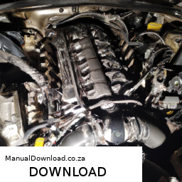
and no excessive play exists.

– **Reassemble Engine Components**
– Replace covers and components that were removed. Ensure all screws and bolts are tightened to the appropriate specifications.

– **Reconnect Battery and Test**
– Reconnect the battery and perform a test run of the engine. Listen for any unusual noises that might indicate improper installation.

– **Final Inspection**
– After the test run, recheck torque on all fasteners and perform a final inspection to ensure everything is secure and functioning correctly.

### Safety and Precautions

– Always wear safety gear, including gloves and goggles, to protect yourself during mechanical work.
If unsure about any step, consult a professional mechanic or refer to the service manual for guidance.
dispose of any old oil or parts according to local regulations.

By following these steps and utilizing the required tools, you can effectively adjust the gear ratio on a Cummins B V4 or V6 engine, optimizing its performance for your specific needs.
The license plate light is a crucial automotive component designed to illuminate the rear license plate of a vehicle. This small yet significant light enhances visibility and ensures that the license plate is easily readable in low-light conditions, such as during nighttime or inclement weather. Typically, the license plate light is mounted on or near the rear of the vehicle, often integrated into the trunk lid, bumper, or a dedicated housing.

Functionally, the license plate light serves important legal and safety purposes. Most jurisdictions require that license plates are clearly visible at all times, and a functioning license plate light helps drivers comply with these regulations. Additionally, a well-lit license plate can assist law enforcement in identifying vehicles during nighttime operations, thereby contributing to overall road safety.

The license plate light usually consists of a housing that contains a bulb, which can be an incandescent, halogen, or LED type, depending on the vehicle’s design and the owner’s preferences. LED lights have become increasingly popular due to their energy efficiency, longer lifespan, and brighter illumination compared to traditional bulbs. Maintenance of the license plate light generally involves checking the bulb’s functionality and replacing it when necessary. Overall, while small in size, the license plate light plays a vital role in vehicle safety, compliance, and visibility on the road.

Download Saturn LW300 Workshop Repair And Service Manual –

purchase
Certainly! click here for more details on the download manual…..


    2005 saturn l300 valve cover gasket replacement 2005 saturn l300 valve cover gasket replacement – This is the 2nd video to sort of a 3 part video. first video was last week how to …

    Solution Saturn L300 Throttle Body Clicking No Start 2001 Saturn L300 throttle body clicks and car doesn’t start. This is a detailed description of the problem and how I fixed it. I used a …

Here’s a step-by-step guide on how to replace the shift solenoid on a Saturn LW300, presented in reverse order:

### Reassembly Steps:

1. **Reconnect the Battery**:
– Reconnect the negative battery cable and ensure it’s tightly secured.

2. **Reinstall the Transmission Pan**:
– Position the transmission pan back onto the transmission.
– Install the new gasket (if applicable) and secure the pan with bolts, tightening them to the manufacturer’s specifications.

3. **Refill Transmission Fluid**:
– Using a funnel, pour the recommended type and amount of transmission fluid into the dipstick tube.
– Start the engine and allow it to run for a few minutes. Check the fluid level and add more if necessary.

4. **Reconnect Electrical Connector**:
– Reconnect the electrical connector to the shift solenoid, ensuring it clicks into place.

5. **Remove the Old Shift Solenoid**:
– Disconnect the wiring harness and any retaining clips or bolts securing the solenoid to the transmission.
– Carefully pull the old solenoid out of its mounting.

6. **Install the New Shift Solenoid**:
– Insert the new solenoid into its designated mounting spot.
– Secure it with the appropriate bolts or clips and reconnect the wiring harness.

### Preparation Steps:

7. **Lift the Vehicle**:
– Use a jack to lift the vehicle safely and secure it with jack stands.

8. **Drain the Transmission Fluid**:
– Place a drain pan under the transmission and remove the drain plug (if applicable) or loosen the transmission pan bolts to allow fluid to drain out.

9. **Remove the Transmission Pan**:
– Carefully unscrew and remove the transmission pan to access the shift solenoid.

10. **Locate the Shift Solenoid**:
– Identify the shift solenoid within the transmission assembly. It is usually located near the valve body.

### Tools and Materials Needed:

– New shift solenoid
– Transmission pan gasket (if necessary)
– Basic hand tools (sockets, wrenches)
– Torque wrench
– Transmission fluid
– Drain pan
– Jack and jack stands

### Safety Precautions:

– Always ensure the vehicle is on a flat surfacedownload Saturn LW300 workshop manual and securely lifted.
– Wear gloves and safety goggles to protect against fluid spills and debris.
– Dispose of old transmission fluid properly at a recycling center.

By following these steps in reverse order, you can successfully replace the shift solenoid in a Saturn LW300. Always consult your vehicle’s service manual for specific instructions and torque specifications.
A knock sensor is an essential component in modern internal combustion engines, designed to detect engine knocking, also known as pre-ignition or detonation. Engine knocking occurs when the air-fuel mixture in the combustion chamber ignites prematurely, leading to a knocking or pinging sound. This phenomenon can cause significant damage to engine components if left unaddressed, including piston damage, cylinder head cracking, and decreased performance.

The knock sensor typically consists of a piezoelectric element that generates an electrical voltage when subjected to vibrations caused by knocking. It is usually mounted on the engine block or cylinder head, strategically positioned to accurately pick up vibrations from the combustion process. When knocking is detected, the sensor sends a signal to the engine control unit (ECU), which then adjusts the engine’s ignition timing or fuel mixture to mitigate the knocking. This real-time adjustment not only protects the engine from potential damage but also optimizes performance and fuel efficiency.

In addition to its protective role, the knock sensor contributes to the overall efficiency of the engine. By allowing the ECU to optimize performance under various load conditions, the knock sensor helps maintain smooth engine operation and enhances fuel economy. As fuel quality and engine conditions vary, the knock sensor plays a crucial role in ensuring that the engine operates within safe parameters, making it a vital component in contemporary automotive engineering.

Download 2007-2014 Fiat Abarth 500 Service & Repair Manual –

owners manual
Repairing the transmission cooler on a Fiat Abarth 500 is a task that requires careful attention and some mechanical skill. click here for more details on the download manual…..


    Fiat 500 Abarth Takeoff and Exhaust sound Stock Exhaust to my Fiat 500 Abarth.

    2015 Fiat 500 Abarth Part Out: J & J Auto Wrecking Test Video Stock # PFFA232 Today we take a look at this 2015 Fiat 500 Abarth that we are parting out here at J&J Auto Wrecking. Looking for parts from this car …

Below is a detailed guide on how to perform this repair, including descriptions of every component involved.

### Tools and Materials Needed

1. **Tools:**
– Socket set (metric)
– Wrench set (metric)
– Screwdrivers (flathead and Phillips)
– Pliers
– Torque wrench
transmission fluid pump (optional)
– Oil catch pan
– Shop towels/rags

2. **Materials:**
– Replacement transmission cooler (if needed)
– New transmission fluid
– New rubber O-rings or seals (if applicable)
– Thread sealant (if applicable)
– Gasket maker (if applicable)

### Step-by-Step Guide

#### Step 1: Prepare the Vehicle
1. **Safety First:**
– Park the vehicle on a flat surface and engage the parking brake.
– Disconnect the negative terminal from the battery to prevent any electrical issues.

2. **Lift the Vehicle:**
– Use a hydraulic jack to lift the front of the vehicle and secure it on jack stands for safety.

#### Step 2: Drain the transmission Fluid
1. **Locate the transmission Drain Plug:**
– Underneath the vehicle, locate the transmission oil pan. The drain plug is typically found on the bottom of the pan.

2. **Drain the Fluid:**
– Place an oil catch pan under the drain plug, remove the plug using the appropriate socket, and allow the fluid to completely drain out.

#### Step 3: Remove the transmission Cooler
1. **Locate the transmission Cooler:**
– The transmission cooler is usually mounted in front of the radiator. It consists of a series of tubes and fins and may be integrated with the radiator.

2. **Disconnect Hoses:**
– Identify the inlet and outlet hoses connected to the cooler. Use pliers to loosen the clamps and gently pull off the hoses. Be prepared for any residual fluid to leak out.

3. **Remove Mounting Bolts:**
– Locate the bolts securing the cooler to the vehicle frame or radiator. Use a socket wrench to remove these bolts.

4. **Extract the Cooler:**
– Carefully pull the cooler out from its mounting position. Take care not to damage any surrounding components.

#### Step 4: Inspect the Cooler
1. **Check for Damage:**
– Inspect the cooler for any visible signs of damage, such as cracks, corrosion, or bent fins. If the cooler is damaged, it will need to be replaced.

2. **Clean the Area:**
– Before installing a new cooler (or repairing the old one), clean the mounting area and the surrounding components to remove any debris or old fluid.

#### Step 5: Install the New Cooler (or Repair)
1. **Install New Cooler:**
– If you are installing a new cooler, align it with the mounting points and secure it with the bolts you previously removed. Tighten the bolts to the manufacturer’s specified torque.

2. **Reconnect Hoses:**
– Attach the inlet and outlet hoses to the coolerdownload Fiat Abarth 500 workshop manual and secure them with the clamps. Ensure there are no leaks at the connections.

3. **Repair Option:**
– If you are repairing the cooler (such as soldering leaks), ensure that all repairs are done properly and that the cooler is leak-free before reinstallation.

#### Step 6: Refill transmission Fluid
1. **Locate the Fill Plug:**
find the transmission fill plug, which is usually located on the side of the transmission.

2. **Refill Fluid:**
– Using a transmission fluid pump, fill the transmission with the appropriate type and amount of transmission fluid as specified in the owner’s manual.

3. **Check Fluid Level:**
– After filling, check the fluid level using the dipstick (if applicable) or the fill plug, and add more fluid if necessary.

#### Step 7: Final Steps
1. **Reconnect Battery:**
– Once everything is reassembled, reconnect the negative battery terminal.

2. **Test Drive:**
– Start the vehicle and let it idle for a few minutes. Check for any leaks around the cooler and hoses. Take the vehicle for a short test drive to ensure the transmission operates smoothly.

3. **Final Check:**
– After the test drive, recheck the fluid level and top off if necessary.

### Conclusion

Repairing or replacing the transmission cooler on a Fiat Abarth 500 can be a challenging task, but with the right tools and careful attention to detail, it can be completed successfully. Always refer to the vehicle’s service manual for specific instructions and specifications, and don’t hesitate to consult a professional mechanic if you’re unsure about any part of the process.
The intake air temperature (IAT) sensor is a critical component in modern internal combustion engines, playing a vital role in optimizing engine performance and efficiency. This sensor measures the temperature of the air entering the engine’s intake manifold. The data it gathers is essential for the engine control unit (ECU) to make real-time adjustments to the engine’s fuel-air mixture and ignition timing.

Typically located near the air intake or in the intake manifold, the IAT sensor operates using either a thermistor or a thermocouple. As the temperature of the incoming air changes, the resistance or voltage output of the sensor also changes, providing the ECU with accurate temperature readings. These readings are crucial because the density of air varies with temperature; cooler air is denser and contains more oxygen, while warmer air is less dense.

By analyzing the temperature data, the ECU can adjust fuel injection rates and ignition timing accordingly, ensuring optimal combustion. This process enhances engine performance, improves fuel efficiency, and reduces emissions. A faulty IAT sensor can lead to poor engine performance, increased fuel consumption, and higher emissions, making it essential for vehicle maintenance. Overall, the intake air temperature sensor is a small but significant component that contributes to the complex dynamics of modern engine management systems.