Download BMW 535 535i 1994 Factory Service Repair Manual –

book store
Certainly! click here for more details on the download manual…..


    How to replace Axles and Brakes | BMW 535i xdrive F10 Replacing my worn out axles and brake pads with rotors on the front and rear of the 535i This video may contain affiliate links, …

    One bad day for a customer! CAR WIZARD found TWO insanely unrelated issues at time on '12 BMW… This car perfectly explains why the CAR WIZARD ‍♂️ hates BMWs! Customer brings in his car only to find two totally unrelated …

The shift interlock system in a BMW 535i (or similar models) is designed to prevent the driver from shifting out of “Park” without pressing the brake pedal. If you’re experiencing issues with the shift interlock, it may need some repair or adjustment. Here’s a simple guide to help you understand and potentially fix it.

### Tools and Materials Needed:
– Screwdriver (flathead and Phillips)
– Pliers
– Socket set or wrench (if needed)
– Flashlight (for better visibility)
– Replacement parts (if necessary, depending on the issue)

### Steps for Shift Interlock Repair:

1. **Safety First:**
– Make sure the car is parked on a flat surface with the engine off. Engage the parking brake for added safety.

2. **Locate the Shift Interlock System:**
– The shift interlock mechanism is usually located underneath the gear shifter. In many BMW models, you may need to remove a cover or trim piece to access it.

3. **Remove the Gear Shift Cover:**
– Use a screwdriver (or your hands) to carefully pry off the cover surrounding the gear shift. Be gentle to avoid breaking any clips or connectors.

4. **Inspect the Mechanism:**
– With the cover removed, locate the shift interlock solenoid (a small electrical component) and the linkage that connects it to the gear shifter. Check for any visible signs of damage, such as broken parts or loose connections.

5. **Check the Brake Switch:**
– The shift interlock system is activated By the brake pedal. Make sure the brake light switch (which is usually located above the brake pedal) is functioning properly. If the brakes lights don’t turn on when you press the pedal, you may need to replace the brake switch.

6. **Test the Shift Interlock:**
– While someone presses the brake pedal, try moving the gear shift out of “Park.” If it shifts smoothly, the interlock issue might be resolved. If not, you may need to look deeper into the solenoid or linkage.

7. **Repair or Replace Parts:**
– If you identify any broken or damaged components, you can either repair them or replace them. For example, if the solenoid is faulty, you’ll need to disconnect it from its wiring and replace it with a new one.

8. **Reassemble Everything:**
– Once you’ve repaired or replaced any damaged parts, carefully reassemble the cover and any other components you removed. Make sure everything is securely fastened.

9. **Test the System:**
– Reconnect the battery (if disconnected) and test the gear shift again. With the brake pedal pressed, see if you can now shift out of “Park.”

10. **Seek Professional Help If Needed:**
– If after all these steps, the issue persists, it might be best to take the vehicle to a professional mechanic. There could be more complex electrical issues involved.

### Tips:
– **Keep Track of screwsdownload BMW 535 535i workshop manual and Parts:** Use a small container to hold any screws or small parts you remove so they don’t get lost.
– **Take Photos:** If you’re unsure about how things fit together, take photos during disassembly to help with reassembly.
– **Consult the Manual:** If you have a service manual for your BMW, refer to it for specific details regarding the shift interlock system.

By following these steps, you should be able to troubleshoot and potentially repair the shift interlock system in your BMW 535i. Good luck!
The clutch fork is a crucial component in manual transmission vehicles, serving as an intermediary between the clutch pedal and the clutch assembly. Its primary function is to engage and disengage the clutch, allowing the driver to shift gears smoothly. Typically made from durable materials like steel or cast iron, the clutch fork is engineered to withstand the stresses and strains associated with the operation of the clutch system.

When the driver presses the clutch pedal, a mechanism—often a hydraulic or cable system—transmits this action to the clutch fork. The fork then pivots on a shaft, pushing against the release bearing, which in turn disengages the clutch plate from the flywheel. This disengagement is essential for shifting gears without grinding or damaging the transmission.

The design of the clutch fork may vary depending on the vehicle’s make and model, but it generally features a forked shape that allows it to accommodate the release bearing effectively. Over time, clutch forks can experience wear or damage, which may lead to issues such as difficulty in shifting gears or even complete clutch failure. Regular inspection and maintenance can help ensure the longevity and proper functioning of this vital component, contributing to a smoother driving experience. In summary, the clutch fork plays an indispensable role in the operation of a manual transmission, facilitating seamless gear changes and overall vehicle performance.

Download Kia Optima Complete Workshop Service Repair Manual 2005 2006 2007 2008 2009 2010 –

repairs
Tire rotation is an essential maintenance procedure that helps ensure even tire wear and prolongs the lifespan of your tires. click here for more details on the download manual…..


    HOW TO REPLACE IGNITION COILS ON KIA OPTIMA | HYUNDAI | 2.0L | 4-CYLINDER | EASY DIY | STEP BY ST… In this video I will demonstrate how to change the ignition coil packs on a 2015 Kia Optima SXL Turbo 2.0L 4-Cylinder.

    The FIRST things to do when modifying your Kia Optima #shorts

For a Kia Optima, the process can be done at home with the right tools and knowledge. Below is a detailed guide on how to perform a tire rotation on a Kia Optima, including every necessary component.

### Tools and Equipment Needed:

1. **Jack**: A hydraulic floor jack or scissor jack to lift the vehicle.
2. **Jack Stands**: To support the vehicle once it’s lifted.
3. **Lug Wrench**: A cross wrench or a socket wrench with the appropriate socket size to remove the lug nuts.
4. **Torque Wrench**: To ensure that lug nuts are tightened to the manufacturer’s specifications.
5. **Tire Pressure Gauge**: To check and adjust tire pressures after rotation.
6. **Gloves**: To keep your hands clean and protected.
7. **Safety Glasses**: To protect your eyes while working.

### Steps for Tire Rotation:

#### 1. Preparation

– **Park on a Level Surface**: Ensure the car is on a flat surface to prevent rolling.
– **Engage the Parking Brake**: This prevents the car from moving while you work.
– **Gather Tools**: Have all your tools easily accessible.

#### 2. Loosening Lug Nuts

– **Loosen the Lug Nuts**: Before lifting the car, use the lug wrench to slightly loosen the lug nuts on all four tires. Turn them counter-clockwise, but do not remove them completely.

#### 3. Lifting the Vehicle

– **Position the Jack**: Refer to the Kia Optima owner’s manual to find the recommended jacking points, typically located near the front and rear wheels.
– **Lift the Vehicle**: Pump the jack handle to raise the vehicle until the tires are off the ground.
– **Place Jack Stands**: Once the vehicle is lifted, place jack stands under the vehicle at the recommended points to provide additional support.

#### 4. Removing the Tires

– **Remove Lug Nuts**: Finish removing the lug nuts completely using the wrench and set them aside in a safe place.
– **Remove Tires**: Carefully pull the tires straight off the wheel hub.

#### 5. Rotating Tires

– **Identify Tire Positions**: For a Kia Optima, the recommended rotation pattern for non-directional tires is usually:
– Front tires move to the rear on the same side.
– Rear tires cross to the front (the left rear goes to the right front and the right rear goes to the left front).

– **Install Tires**: Place the tires in their new positions, ensuring they are seated properly on the wheel hub.

#### 6. Replacing Lug Nuts

– **Hand-Tighten Lug Nuts**: start threading the lug nuts by hand to avoid cross-threading. Hand-tighten them in a star pattern to ensure even pressure.

#### 7. Lowering the Vehicle

– **Remove Jack Stands**: Carefully take out the jack stands.
– **Lower the Vehicle**: Slowly lower the vehicle using the jack until it is back on the ground.

#### 8. tightening Lug Nuts

– **Tighten Lug Nuts**: Using the torque wrench, tighten the lug nuts to the manufacturer’s specified torque (usually around 80-100 ft-lbs for a Kia Optima). Again, use a star pattern to ensure even distribution of pressure.

#### 9. Check Tire Pressure

– **Check Tire Pressure**: Use a tire pressure gauge to check the air pressure in each tire. Adjust as necessary to match the recommended pressure found in the driver’s side door jamb.

#### 10. Final Inspection

– **Inspect Tires**: Look for any signs of damage, uneven wear, or foreign objects in the tread.
– **Test Drive**: Take the vehicle for a short test drive to ensure everything feels normal.

### Maintenance Reminder:

– **Frequency of Rotation**: Tire rotation should generally be performed every 5,000 to 7,500 miles or as recommended in your vehicle’s owner’s manual.
– **Check Alignment**: If you notice uneven tire wear after rotation, it may be an indication of misalignment that needs to be addressed.

By following these steps, you can successfully rotate the tires on your Kia Optima, helping to maximize their lifespandownload Kia Optima workshop manual and improve your vehicle’s handling.
Transmission fluid is a vital lubricant specifically designed for the smooth operation of a vehicle’s transmission system. This fluid plays a crucial role in facilitating the transfer of power from the engine to the wheels, ensuring that the vehicle shifts gears seamlessly and operates efficiently. Transmission fluid is typically formulated with a blend of base oils and additives that enhance its performance characteristics, such as viscosity, thermal stability, and anti-wear properties.

One of the primary functions of transmission fluid is to lubricate the moving parts within the transmission, reducing friction and wear. This not only extends the lifespan of the transmission components but also helps to maintain optimal performance. Additionally, transmission fluid acts as a hydraulic fluid, enabling the transmission to engage and disengage gears smoothly. This hydraulic function is essential for automatic transmissions, where the fluid pressure controls the shifting process.

Moreover, transmission fluid serves a critical role in cooling the transmission system. It absorbs heat generated during operation and dissipates it, preventing overheating, which can lead to significant damage. Different types of transmissions, such as automatic, manual, or continuously variable transmissions (CVTs), require specific types of transmission fluid, each with unique properties tailored to their operational needs. Regular maintenance, including checking and changing transmission fluid, is essential for ensuring the longevity and reliability of a vehicle’s transmission system, making it a key component in automotive care.

Download KOMATSU WA380-1, WA420-1 Wheel Loader Operation & Maintenance Manual (S/N: 20001 and up) –

owners manual
Replacing a catalytic converter on a Komatsu WA380-1 or WA420-1 wheel loader can seem daunting, but with a basic understanding and the right tools, you can accomplish this task. click here for more details on the download manual…..


    Parking brake release solenoid

    2014 KOMATSU WA380-7 RUBBER TIRE LOADER For Sale https://www.machinerytrader.com/listings/other-items/for-sale/208588499?LP=MAT EROPS, NO BUCKET, 23.5R25 TIRES, …

Below is a step-by-step guide tailored for someone with little mechanical experience.

### Tools and Materials Needed:
1. **Safety Gear**: Safety glasses, gloves, and a hard hat.
2. **Basic Tools**:
– Wrenches (typically 10mm, 12mm, or 14mm)
– Socket set
– Ratchet
– Torque wrench
– Pliers
– Screwdriver
3. **New Catalytic Converter**: Make sure you have the correct model for your Komatsu WA380-1 or WA420-1.
4. **Gasket**: For sealing the connection.
5. **Shop Rags**: For cleaning up.

### Step-by-Step Replacement Process:

#### Step 1: Safety First
– **Park the Loader**: Ensure the loader is parked on a flat surface and the engine is off.
– **Engage the Parking Brake**: This will prevent the machine from moving unexpectedly.
– **Disconnect the Battery**: Disconnect the negative terminal to prevent any electrical issues while working.

#### Step 2: Locate the Catalytic Converter
– **Find the Exhaust System**: The catalytic converter is located along the exhaust system, usually between the engine and the muffler.
– **Identify the Converter**: It is a cylindrical component, often covered in a heat shield.

#### Step 3: Remove the Old Catalytic Converter
– **Access the Converter**: Depending on the design, you might need to remove some protective covers or heat shields to reach the converter.
– **Loosen Bolts**: Using the appropriate wrench or socket, carefully loosen the bolts securing the catalytic converter to the exhaust system. If they are rusted, you might need to apply some penetrating oil.
– **Remove the Converter**: Once the bolts are removed, gently pull the catalytic converter away from the exhaust pipes. You might need to twist or turn it slightly to free it.

#### Step 4: Prepare for the New Converter
– **Clean the Area**: Use a rag to clean the exhaust pipe flanges where the new converter will attach. This helps ensure a good seal.
– **Check Gasket**: If the old gasket is worn out, replace it with a new one.

#### Step 5: Install the New Catalytic Converter
– **Position the New Converter**: Align it with the exhaust pipes.
– **Secure with Bolts**: Hand-tighten the bolts first to hold the converter in place, then use your wrench to tighten them securely. Be careful not to overtighten, as this can damage the converter or exhaust pipes.
– **Replace Heat Shields**: If you removed any heat shields, reattach them now.

#### Step 6: Reconnect the Battery
– **Reconnect the Battery**: Attach the negative terminal back to the battery.

#### Step 7: Test the Loader
– **Start the Engine**: Turn on the loader and let it idle for a few minutes.
– **Check for Leaks**: Listen for any unusual soundsdownload KOMATSU WA380 1 WA420 1 Wheel Loader Operation S N 1 up workshop manual and look for exhaust leaks around the catalytic converter area. If you see any leaks, you may need to tighten the bolts further.

### Final Tips:
– **Consult the Owner’s Manual**: If you have access to the loader’s manual, refer to it for specific instructions or torque specifications.
– **Seek Help if Needed**: If at any point you feel uncomfortable, don’t hesitate to ask for help from someone with more mechanical experience.

### Conclusion
Replacing the catalytic converter on a Komatsu WA380-1 or WA420-1 wheel loader requires basic tools and a careful approach. By following these steps, you can complete the replacement and help ensure the machine runs efficiently and meets emission standards. Always prioritize safety and don’t hesitate to seek assistance if needed.
A pressure plate is a crucial component in a vehicle’s clutch system, primarily found in manual transmission vehicles. Its primary role is to engage and disengage the clutch, allowing for smooth shifting between gears. The pressure plate is a metal disc that is mounted on the flywheel, and it works in conjunction with the clutch disc and release bearing.

When the driver presses the clutch pedal, the release bearing pushes against the pressure plate, causing it to move away from the clutch disc. This disengagement allows the engine to rotate independently of the transmission, enabling the driver to shift gears without grinding or damaging the gearbox. When the pedal is released, a series of springs within the pressure plate push it back into contact with the clutch disc, re-engaging the clutch and allowing power from the engine to be transmitted to the wheels.

The pressure plate is designed to withstand significant forces and heat generated during the engagement and disengagement process. It often features a series of springs that provide the necessary clamping force to hold the clutch disc tightly against the flywheel, ensuring efficient power transfer. Over time, however, wear and tear can lead to issues such as slipping or difficulty in shifting gears, necessitating replacement to maintain optimal vehicle performance. Understanding the role and functionality of the pressure plate is essential for diagnosing clutch-related issues and ensuring the longevity of a vehicle’s transmission system.

Download 1990 Chevrolet Sprint Service & Repair Manual Software –

book store
Certainly! click here for more details on the download manual…..


    The 1988 Chevy Sprint Metro is finally LEGAL !!! Thank you for watching my latest video. I hope you enjoyed it watching my 1988 Chevrolet Sprint Metro. If you did, please give it a …

    TWO WAYS to remove a stuck CV axle. Steve shows you two ways to remove a CV axle that has a friction ring retainer. Both methods are an easy DIY job. Amazon …

Here’s a reverse order guide for flywheel resurfacing on a Chevrolet Sprint:

### 6. **Reinstall the Flywheel:**
– Align the flywheel with the crankshaft.
– Secure it in place using the bolts and torque them to the manufacturer’s specifications.

### 5. **Install the Clutch:**
– Position the clutch disc onto the resurfaced flywheel.
– Align the clutch cover over the clutch disc and secure it with bolts, tightening them in a crisscross pattern to ensure even pressure.

### 4. **Remove the Flywheel:**
– Unbolt the flywheel from the crankshaft.
– Carefully pull it off and set it aside for resurfacing.

### 3. **Prepare the flywheel for Resurfacing:**
– Clean the flywheel using a degreaser to remove any oil or grime.
– Inspect for cracks or excessive wear before proceeding to the machine shop.

### 2. **Transport to Machine Shop:**
– Take the flywheel to a machine shop that specializes in resurfacing.
– Discuss the condition of the flywheel with the technician for appropriate resurfacing.

### 1. **Remove Transmission:**
– Begin by lifting the vehicle and securely supporting it on jack stands.
– Disconnect the battery, and remove the necessary components (like the shift linkage and starter) to access the transmission.
– Unbolt and remove the transmission from the engine.

Following these steps in reverse order ensures a clear understanding of the process involved in resurfacing a flywheel on a Chevrolet Sprint. Always refer to a service manual for specific torque specificationsdownload Chevrolet Sprint workshop manual and procedures, and ensure safety precautions are taken during the process.
The ignition switch is a crucial component in a vehicle’s electrical system, responsible for starting the Engine and controlling the electrical power supply to various systems. Located on the steering column or dashboard, it is typically operated by a key or a push-button mechanism in modern vehicles. The ignition switch serves multiple functions, including activating the battery power to the ignition system, fuel pump, and electronic components necessary for the vehicle to start and operate.

When the key is turned or the button is pressed, the ignition switch allows electrical current to flow from the battery to the ignition coil, which generates a high-voltage spark to ignite the fuel-air mixture in the engine’s cylinders. Additionally, the switch engages the starter motor, which cranks the engine, initiating the combustion process. Most ignition switches have multiple positions, including “Off,” “Accessory,” “On,” and “Start,” each serving specific functions. The “Accessory” position allows for the operation of electrical components like the radio and power windows without starting the engine, while the “On” position powers the vehicle’s essential systems.

Over time, ignition switches can wear out or develop faults, leading to difficulties in starting the vehicle or unexpected electrical issues. Therefore, regular maintenance and prompt replacement of a failing ignition switch are essential for ensuring reliable vehicle operation and safety.

Download FERRARI DINO 308 GT4 Service Repair Manual –

online
Replacing the clutch plate on a Ferrari Dino 308 GT4 is a complex process that requires careful attention to detail and a good understanding of automotive mechanics. click here for more details on the download manual…..


    Ferrari 308 GT4 Dino Underside Tour A look at the underside of a Ferrari 308 GT4 dino.

    Radiator and pipes removal on the Ferrari 308 | Restoration | Episode 3 So we decided to remove the radiator. What a mess this is!! What shall we do? replace or repair? And how bad is the rusty frame?

below is a step-by-step guide outlining the necessary tools and procedures for this task.

### Tools and Equipment Needed

– **Socket Set**: A complete set of metric sockets, especially 10mm, 13mm, 17mm, and 19mm, to remove various bolts.
– **Ratchet and Extensions**: A ratchet with extensions for reaching difficult areas.
– **Torque Wrench**: To ensure all bolts are tightened to the manufacturer’s specifications.
– **Pliers**: Needle-nose and regular pliers for gripping and pulling components.
– **Screwdrivers**: Flat-head and Phillips screwdrivers for various fasteners.
– **Clutch Alignment Tool**: A specific tool or a makeshift tool to align the new clutch plate properly.
– **Jack and Jack Stands**: A hydraulic jack to lift the car Safely and jack stands to secure it.
– **Transmission Jack**: To support and lower the transmission safely.
– **Shop Manual**: A detailed service manual for the Dino 308 GT4 for reference on specifications and procedures.
– **Clean Rags**: For cleaning components during the process.
– **Brake Cleaner**: To clean the clutch components before installation.
– **New Clutch Kit**: Including the clutch plate, pressure plate, and release bearing.
– **Lubricants**: High-temperature grease for the release bearing and other moving parts.

### Procedure for Clutch Plate Replacement

– **Preparation**:
– Park the vehicle on a flat surface and engage the parking brake.
– Disconnect the battery to ensure safety during the process.

– **Lift the Vehicle**:
– Use a hydraulic jack to raise the rear of the vehicle.
– Secure the vehicle with jack stands for safety.

– **Remove the Exhaust System**:
– Disconnect the exhaust pipes from the headers using appropriate socket sizes.
– Remove any hangers and support brackets to free the exhaust.

– **Drain Transmission Fluid**:
– Locate the transmission drain plug and drain the fluid into a suitable container.

– **Remove the Transmission**:
– Disconnect the driveshaft from the transmission, noting the orientation for reinstallation.
– Remove any electrical connections, speedometer cables, and linkages for the clutch and shifter.
– Support the transmission with a transmission jack.
– Unbolt the transmission from the engine block, carefully lowering it to the ground.

– **Accessing the Clutch Assembly**:
– Once the transmission is removed, the clutch assembly is accessible.
– Inspect the clutch for wear and damage.

– **Remove the Old Clutch Plate**:
– Remove the pressure plate bolts, typically in a star pattern to avoid warping.
– Carefully detach the pressure plate and clutch plate from the flywheel.
– Take note of the orientation of the clutch components for proper alignment during reassembly.

– **Clean the Flywheel and Components**:
– Use brake cleaner and rags to clean the flywheel surface and other components, removing any grease or debris.
– Inspect the flywheel for scoring or damage; it may require resurfacing if worn.

– **Install the New Clutch Plate**:
– Position the new clutch plate onto the flywheel, ensuring proper alignment.
– Use a clutch alignment tool to keep the plate centered.
– Attach the pressure platedownload FERRARI DINO 308 GT4 workshop manual and tighten the bolts in a star pattern to the specified torque setting.

– **Reinstall the Transmission**:
– Carefully lift the transmission back into position using the transmission jack.
– Reattach the transmission to the engine block, ensuring all bolts are properly torqued.
– Reconnect the driveshaft, ensuring it is oriented as it was removed.

– **Reconnect Additional Components**:
– Reattach the exhaust system, ensuring all bolts and hangers are securely fixed.
– Reconnect any electrical wiring, cables, and linkages that were previously disconnected.

– **Refill Transmission Fluid**:
– Replace the transmission drain plug and refill the transmission with the appropriate fluid.

– **Final Checks**:
– Reconnect the battery.
– Check all connections for tightness and ensure nothing is left loose or unconnected.

– **Test Drive**:
– Start the vehicle and allow it to warm up.
– Test the clutch operation by engaging and disengaging the clutch several times.
– Take the vehicle for a short test drive to ensure the clutch operates smoothly without slipping.

### Conclusion

Replacing the clutch plate on a Ferrari Dino 308 GT4 requires patience and precision. Ensure to follow safety precautions and consult the shop manual for specific torque settings and procedures. If unsure about any step, consider consulting a professional mechanic familiar with classic Ferraris.
A seat cover is an accessory designed to protect, enhance, or personalize the seats of a vehicle. Typically made from a variety of materials such as fabric, leather, neoprene, or vinyl, seat covers serve multiple purposes, including safeguarding the original upholstery from wear and tear, stains, and spills. They are especially beneficial for families with children or pet owners, as they provide a barrier against dirt, hair, and other messes that can accumulate on vehicle seats.

In addition to protection, seat covers can significantly improve the aesthetic appeal of a car’s interior. They come in a wide range of colors, patterns, and designs, allowing vehicle owners to express their personal style and complement the overall look of their car. Custom-fit seat covers are also available, which are tailored to the specific dimensions and contours of a vehicle’s seats, ensuring a snug and secure fit that enhances comfort.

Installation of seat covers can be straightforward, with many designs featuring elastic straps, hooks, or Velcro to ensure they stay in place. Some seat covers are even designed to be machine washable, making maintenance easy and convenient. Overall, seat covers are a practical investment for anyone looking to maintain the longevity of their vehicle’s interior while adding a touch of individuality.

Download Lotus Esprit S4 V-8 1993 Service Repair Workshop Manual –

fix
Replacing the spark plugs on a Lotus Esprit S4 V8 is a task that requires careful attention to detail and an understanding of the vehicle’s components. click here for more details on the download manual…..


    Top Gear ~ Lotus Esprit Review New videos every Monday | Wednesday | Friday Top Gear Playlist …

    The Lotus Esprit V8 Is an Underrated Exotic Sports Car CHECK OUT THIS ESPRIT ON CARS & BIDS! https://carsandbids.com/auctions/rNG2nAp5/1999-lotus-esprit-v8 Lotus Esprit V8 …

Below is a detailed guide on how to perform this task, including descriptions of every component involved.

### Tools and Materials Needed
1. **Socket Wrench Set**: To remove the spark plug sockets. A 5/8 inch socket is typically used for spark plugs.
2. **Torque Wrench**: Essential for tightening the new spark plugs to the manufacturer’s specifications.
3. **Extension Bars**: To reach the spark plugs, which may be located in tight spaces.
4. **Spark Plug Gap Tool**: To measure and adjust the gap on new spark plugs.
5. **Anti-seize Compound**: To apply to the threads of the new spark plugs.
6. **Dielectric Grease**: To protect the electrical connections.
7. **Cleaner/Brake Cleaner**: To clean any debris from the area around the spark plugs before removal.
8. **Shop Towels/Rags**: For cleanup and to wipe any spills.
9. **Safety Glasses**: To protect your eyes during the process.

### Steps to Replace Spark Plugs

#### 1. Preparation
– **Ensure Safety**: Park the vehicle on a flat surface and engage the parking brake. Allow the engine to cool completely before starting the spark plug replacement.
– **Disconnect the Battery**: Remove the negative terminal of the battery to prevent any electrical shorts or shocks during the process.

#### 2. Locate the Spark Plugs
– The Lotus Esprit S4 V8 has a V8 engine configuration, with four spark plugs located on each side of the engine. Accessing the plugs may require removing some engine covers or components.

#### 3. Remove Engine Covers
– **Engine Covers**: Depending on the year and specific model of your Esprit, you may need to remove various engine covers. Use a socket wrench to remove any screws or bolts holding these covers in place.

#### 4. Clean the Area
– **Clean Around Spark Plugs**: Use a cleaner or brake cleaner to remove any dirt or debris around the spark plugs. This step is crucial to prevent debris from falling into the combustion chamber when the plugs are removed.

#### 5. Remove the Old Spark Plugs
– **Disconnect Ignition Wires**: Carefully disconnect the ignition wires or coil packs from the spark plugs. Gently twist and pull to avoid damaging the connectors.
– **Use Socket Wrench**: Attach the 5/8 inch socket to the extension bar, and carefully turn counterclockwise to loosen and remove the spark plug. Repeat for each spark plug, taking care to note which wire connects to which plug for reinstallation.

#### 6. Inspect Old Spark Plugs
– **Check Condition**: Examine the removed spark plugs for signs of wear, fouling, or damage. This can provide insight into the engine’s condition and whether further investigation is needed.

#### 7. Prepare New Spark Plugs
– **Check Gap**: Use the spark plug gap tool to check the gap on the new spark plugs. Adjust the gap if necessary to meet the specifications outlined in the owner’s manual.
– **Apply Anti-Seize Compound**: Lightly apply anti-seize compound to the threads of the new spark plugs. Avoid getting any on the electrode or insulator.

#### 8. Install New Spark Plugs
– **Screw in New Plugs**: Carefully insert each new spark plug into its respective hole. download Lotus Esprit S4 V 8 workshop manualHand-tighten initially to avoid cross-threading.
– **Torque Specification**: Once hand-tightened, use the torque wrench to tighten the spark plugs to the manufacturer’s specified torque, typically around 15-20 lb-ft (check your owner’s manual for exact specifications).

#### 9. Reconnect Ignition Wires
– **Reconnect Wires**: Reattach the ignition wires or coil packs to the corresponding spark plugs. Ensure they are seated properly to avoid misfires.

#### 10. Replace Engine Covers
– **Reinstall Covers**: Once all spark plugs are replaced, reinstall any engine covers that were removed earlier. Secure them with the appropriate screws or bolts.

#### 11. Reconnect the Battery
– **Reconnect Battery Terminal**: Reattach the negative terminal of the battery.

#### 12. Start the Engine
– **Test the Engine**: Start the engine and allow it to idle for a few minutes. check for any unusual sounds or misfires.

#### 13. Clean Up
– **Dispose of Old Spark Plugs**: Properly dispose of the old spark plugs and clean the work area.

### Conclusion
Replacing the spark plugs in a Lotus Esprit S4 V8 can be a rewarding project that enhances engine performance and reliability. Always refer to the specific service manual for your vehicle for any unique specifications or procedures. If you are uncomfortable performing this task, consider seeking assistance from a professional mechanic familiar with Lotus vehicles.
A door seal, often referred to as a door weatherstrip or seal gasket, is a critical component in automotive design that serves multiple essential functions. Positioned around the edges of a vehicle’s doors, this flexible strip is primarily made from rubber or foam materials that are engineered to fit snugly against the door frame when the door is closed. The primary purpose of a door seal is to prevent water, air, dust, and noise from entering the cabin of the vehicle, thereby enhancing the comfort and overall driving experience.

In addition to its protective functions, the door seal plays a significant role in improving the vehicle’s energy efficiency. By minimizing airflow leakage, it helps maintain the interior temperature, reducing the strain on heating and cooling systems. This not only contributes to a more pleasant driving experience but also can lead to improved fuel efficiency.

Door seals are designed to withstand various environmental conditions, including extreme temperatures, UV exposure, and moisture, ensuring durability over the lifespan of the vehicle. Over time, these seals can wear out or become damaged, leading to issues such as increased noise levels, water leaks, or drafts. Regular inspection and maintenance of door seals are essential, and replacements can often be performed easily, helping to maintain the integrity and comfort of the vehicle’s interior environment.

Download 2002 BMW 318d (E46) 3 Series OEM Download Service & Repair Manual Software –

workshop
Tire rotation is an essential maintenance task that helps ensure even tire wear and prolongs the life of your tires. click here for more details on the download manual…..


    Hidden Features of the BMW e46 part 2 Here are 5 hidden features of the BMW e46. CHECK OUT MY AMAZON AFFILIATE LINK: …

    What It’s Like To daily drive a bmw e46 in 2023 (not what you may expect)

For a BMW 318d E46, this process is relatively straightforward, even for those with little mechanical experience. Here’s a step-by-step guide to help you through it:

### Tools You’ll Need:
1. **Jack** – To lift the car off the ground.
2. **Jack Stands** – For safety while the car is lifted.
3. **Lug Wrench** – To remove and tighten the wheel nuts.
4. **Tire Pressure Gauge** (optional) – To check tire pressure after rotation.

### Steps for Tire Rotation:

1. **Preparation**:
– **Park on a Level Surface**: Ensure your car is on a flat, stable area. Turn off the engine and set the parking brake.
– **Gather Your Tools**: have your jack, jack stands, and lug wrench ready.

2. **Loosen the Lug Nuts**:
– Before lifting the car, use the lug wrench to slightly loosen (but not remove) the lug nuts on all four wheels. Turn them counterclockwise. This makes it easier to remove them once the car is lifted.

3. **Lift the Car**:
– **Position the Jack**: Refer to your owner’s manual for the proper jacking points on your BMW. Place the jack under the recommended lifting point.
– **Jack Up the Car**: Lift the car until the tires are off the ground. Make sure it’s high enough to access the wheels comfortably.
– **Secure with Jack Stands**: Once the car is lifted, place jack stands under the car to support it. Never rely solely on the jack for safety.

4. **Remove the Wheels**:
– **Take Off the Lug Nuts**: Now that the car is securely lifted, fully remove the lug nuts and take off the wheels. Keep the lug nuts in a safe place where they won’t get lost.

5. **Rotate the Tires**:
– **Understanding Tire Position**: For a BMW 318d E46, the typical rotation pattern is:
– **Front Tires**: Move the front tires to the rear on the same side (e.g., left front to left rear and right front to right rear).
– **Rear Tires**: The rear tires should be moved to the front, but swap sides (e.g., left rear to right front and right rear to left front).
– **Position the Tires**: Place each tire in its new position.

6. **Reattach the Wheels**:
– **Put the Wheels Back On**: Place the wheel onto the hub and hand-tighten the lug nuts. Make sure they are on in a star pattern for even tightening.

7. **Lower the Car**:
– Carefully remove the jack stands and lower the car back to the ground using the jack.

8. **Tighten the Lug Nuts**:
– Once the car is back on the ground, use the lug wrench to fully tighten the lug nuts. Again, do this in a star pattern to ensure even pressure.

9. **Check Tire Pressure** (Optional):
– After rotating, check the tire pressure with a tire gaugedownload BMW 318d E46 3 OEM workshop manual and inflate them to the recommended PSI (found in your owner’s manual or on the driver’s side door jamb).

10. **Final Check**:
– Make sure everything is tight and secure. Store your tools and clean up any mess.

### Maintenance Reminder:
It’s generally recommended to rotate your tires every 5,000 to 7,500 miles (or as specified by your manufacturer) to promote even wear.

By following these steps, you can successfully rotate the tires on your BMW 318d E46 and help maintain the longevity and performance of your vehicle. If you ever feel unsure, don’t hesitate to consult a professional mechanic.
The hood hinge is a crucial component in an automobile that plays a significant role in the function and operation of the vehicle’s hood, also known as the engine cover. Typically made from metal or high-strength plastic, hood hinges are designed to provide a pivot point that allows the hood to open and close smoothly. They are usually located on either side of the hood and are attached to both the car’s body and the underside of the hood.

One of the primary functions of the hood hinge is to support the weight of the hood while allowing it to be lifted and securely held in an open position. This is essential for accessing the engine compartment for maintenance tasks, such as checking fluid levels, replacing parts, or performing repairs. A well-functioning hood hinge ensures that the hood operates smoothly, without sagging or misalignment, which can lead to difficulties in closing the hood properly.

Hood hinges can be susceptible to wear and tear over time due to exposure to the elements, road debris, and regular use. Signs of wear may include difficulty in opening or closing the hood, unusual noises during operation, or visible rust and corrosion. In such cases, the hinges may need to be lubricated or replaced to maintain their functionality and ensure safety while driving. Overall, the hood hinge is a simple yet vital component that contributes to the overall performance and ease of use of a vehicle.

Download Jaguar MK1 Service Manual and Parts Catalogue –

diy
Adjusting the gear selector cable on a Jaguar MK1 can help ensure that the transmission shifts smoothly and accurately. click here for more details on the download manual…..


    Jaguar MK1 3.4 – Mike Hawthorn tribute car – So i have a plan for the interior, Whats your though… Hello again everyone So a little more on the MK1, this is my 3.4 tribute to Mike Hawthorn and it is a very beautiful car but.

    jaguar e type bleeding the rear brakes First thing i forgot to mention in the video is depending on the brake adjustment setting screw position, you may have to depress …

Here’s a step-by-step guide that simplifies the process for someone with little mechanical experience:

### Tools and Materials Needed:
– A wrench or socket set (usually 10mm for the cable)
– A screwdriver (if needed)
– A ruler or measuring tape
– A helper (optional, but can make the process easier)

### Step-by-Step Guide:

1. **Safety First**:
– Ensure the car is parked on a flat surface.
– Turn off the Engine and remove the keys from the ignition.
– Engage the parking brake to prevent the car from rolling.

2. **Locate the Gear Selector Cable**:
– Open the hood of the car.
– Find the gear selector cable. It is usually connected to the gear lever inside the car and runs down to the transmission.

3. **Inspect the Cable**:
– Look for any visible signs of wear, fraying, or damage. If you see any issues, you may need to replace the cable instead of adjusting it.

4. **Identify the Adjustment Points**:
– Find the adjustment point on the cable. This is typically a nut or a clamp that allows you to change the length of the cable. It may be located near the transmission or at the gear lever.

5. **Loosen the Adjustment Nut**:
– Using your wrench, carefully loosen the nut on the adjustment point. Do not remove it completely; just loosen it enough so that you can adjust the cable.

6. **Adjust the Cable**:
pull the cable to make it tighter or push it to make it looser. Ideally, you want to adjust it until the gear lever moves smoothly through all the gears without feeling too tight or too loose.
– If you have a helper, they can sit in the driver’s seat and move the gear lever while you make adjustments to see how it feels.

7. **Check the Gear Shifts**:
– After making adjustments, check the gear shifts. Move the gear lever through all the positions (Park, Reverse, Neutral, Drive) to ensure it engages properly.
– Make sure the lever returns to the correct position when you shift from Drive back to Park.

8. **Tighten the Nut**:
– Once you’re satisfied with the adjustment, tighten the nut securely with your wrench. Be careful not to over-tighten it, as this may damage the cable.

9. **Test Drive**:
– Start the Enginedownload Jaguar MK1 ue workshop manual and take the car for a short test drive. Pay attention to how the transmission shifts. It should feel smooth and responsive.

10. **Final Check**:
– After the test drive, double-check the adjustment nut to ensure it hasn’t loosened during the drive.

### Conclusion:
Adjusting the gear selector cable on a Jaguar MK1 can be a straightforward task if you follow these steps carefully. If you encounter any issues or if the cable seems excessively worn, it’s best to consult a professional mechanic.
The hood latch is a crucial component of a vehicle’s hood system, designed to secure the hood in a closed position while allowing for easy access when needed. Typically made from durable materials like steel or high-strength plastic, the hood latch consists of two main parts: the latch mechanism itself, which is mounted to the vehicle’s body, and the striker or catch, which is attached to the underside of the hood.

When the hood is closed, the latch engages with the striker, locking the hood in place and preventing it from opening during driving. This is essential for safety, as an unsecured hood can obstruct the driver’s view or cause potential accidents. The hood latch can be operated manually from the inside of the vehicle, usually via a lever or pull handle located near the driver’s seat, which releases the latch mechanism and allows the hood to be opened.

In addition to its primary function of securing the hood, the latch is designed with safety features such as a secondary catch to prevent accidental opening while driving. Over time, hood latches can wear out or become damaged due to exposure to the elements, leading to potential issues with hood security. Regular maintenance and inspections are essential to ensure the latch functions properly, contributing to the overall safety and functionality of the vehicle.

Download Vailant Chrysler Slant 6-225 Engine Overhaul Manual –

repair
Adjusting the transmission band on a Chrysler Slant 6 225 engine, particularly in the context of a complete overhaul, involves several steps and requires an understanding of both the transmission system and the engine itself. click here for more details on the download manual…..


    Resurrecting A Mopar 225 Dodge Slant Six – Engine Power S2, E2 On this episode of Engine Power, the team resurrects and hot rods Mopar’s indestructible 6 cylinder – the bulletproof 225 Dodge …

    Valiant Slant 6 Rebuild – Sealing up the sump – Part I I used Aviation gasket sealant for the sump gasket which is cork. Do 1 side first, let it set then do the other. The only RTV sealant …

The Slant 6 engine, which was used in various Chrysler vehicles, often had automatic transmissions, such as the TorqueFlite. The transmission bands are crucial for proper shifting and operation of the transmission.

### Components Involved in Transmission Band Adjustment

1. **Transmission Bands**: These are metal bands that wrap around the transmission drum or housing to engage and disengage gears. There are usually two bands to adjust: the forward band and the reverse band.

2. **Adjusting Screws/Nuts**: These screws or nuts are used to tighten or loosen the bands. They are usually located on the transmission case.

3. **Torque Wrench**: A tool used to apply a specific amount of torque to the adjusting screws, ensuring that they are tightened to the manufacturer’s specifications.

4. **Transmission Manual**: A service manual specific to the vehicle model will provide the torque specifications and adjustment procedures.

5. **Basic Hand Tools**: Wrenches, sockets, and screwdrivers will be needed for disassembly and adjustment.

### steps for Transmission Band Adjustment

#### Preparation
1. **Safety First**: Ensure the vehicle is parked on a level surface, turn off the ignition, and engage the parking brake. It’s also a good idea to disconnect the battery.

2. **Access the Transmission**: Depending on the vehicle, you may need to remove the transmission pan to access the bands. This involves:
– Removing the bolts securing the transmission pan.
– Carefully prying the pan loose and draining the fluid into a pan (if applicable).

#### Adjustment Process
3. **Locate the Bands**: Once you have access to the transmission, locate the forward and reverse bands. They are usually on the side of the transmission and are identifiable by their metal straps.

4. **Identify Adjustment Screws**: Find the adjustment screws, which may be covered by a protective cover or seal. Remove any covers if necessary.

5. **Loosen the Bands**: Before making any adjustments, it is recommended to slightly loosen the adjustment screws to relieve any tension on the bands.

6. **Adjust the Forward Band**:
– **Tightening**: Turn the adjusting screw clockwise until resistance is felt. This is typically done until the band is snug but not overly tight.
– **Set the Torque**: Use a torque wrench to tighten the adjusting screw to the manufacturer’s specified torque (often around 72-96 inch-pounds for the forward band). Consult the service manual for exact specifications.
– **Back Off**: After torquing, it is common to back off the adjustment slightly (usually 1-2 turns) to set the band correctly.

7. **Adjust the Reverse Band**:
– **Tightening**: Similar to the forward band, turn the adjusting screw clockwise until you feel resistance.
– **Set the Torque**: Again, use a torque wrench to tighten to the specified torque (varies by model, but generally around 72-96 inch-pounds).
– **Back Off**: Back off the reverse band adjustment as specified in the manual.

8. **Recheck Adjustments**: After adjusting both download Vailant Chrysler Slant 6 225 Engine Overhaul workshop manual
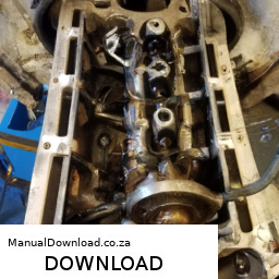
bands, double-check that they are set correctly according to the specifications provided in the service manual.

#### Reassembly
9. **Reinstall the Transmission Pan**: If you removed the pan, replace it with a new gasket to prevent leaks and reinstall the bolts. Tighten them to the specified torque, usually in a crisscross pattern.

10. **Refill Transmission Fluid**: After reassembly, refill the transmission with the appropriate fluid as specified in the manual.

11. **Final Checks**: Start the engine and cycle through the transmission gears while checking for proper operation. Look for leaks around the pan and ensure smooth shifting.

### Final Notes
– **Consult the Manual**: Always refer to the specific vehicle service manual for detailed specifications and procedures, as they can vary by model and year.
– **Fluid Condition**: Check the condition of the transmission fluid; if it is dirty or burnt, consider a fluid change during the overhaul.
– **Test Drive**: After reassembly and adjustments, take the vehicle for a test drive to ensure everything is functioning correctly.

Adjusting the transmission bands will help ensure smooth operation and longevity of the transmission in your Chrysler Slant 6 225 engine.
The windshield wiper is an essential automotive component designed to enhance visibility during adverse weather conditions, primarily rain, snow, and sleet. It consists of a mechanical arm that pivots back and forth across the windshield, equipped with a rubber blade that makes direct contact with the glass surface. The wiper’s primary function is to clear away precipitation, dirt, and debris, ensuring that the driver has a clear line of sight while operating the vehicle.

Windshield wipers operate through a combination of electric motors and a linkage system. When the driver activates the wiper switch, an electric motor initiates movement, causing the arm to sweep across the windshield in a predetermined pattern. Many modern vehicles feature adjustable wiper speeds, allowing drivers to choose between intermittent, slow, and fast settings based on the severity of the weather. Some advanced systems even include rain-sensing technology, which automatically adjusts the wiper speed based on the intensity of the rain.

In addition to their primary function, windshield wipers are often paired with a washer system that sprays a cleaning solution onto the windshield, further aiding in visibility. Regular maintenance of wiper blades is crucial, as worn or damaged blades can lead to streaking or smearing, ultimately compromising safety. Overall, windshield wipers play a vital role in vehicle safety, contributing to driver confidence and road awareness in challenging conditions.

Download Fiero 1984 to 1988 Factory Service Workshop Repair Manual –

book shop
Repairing the gearbox housing on a Pontiac Fiero involves several steps, and I will outline the process in reverse order. click here for more details on the download manual…..


    Car won't start, No Spark. 1986 Pontiac Fiero Ignition Module Trouble Shooting, Cost Free Rep… High Definition Video with concise information for Automotive enthusiasts.

    Putting NEW Wheels On My Pontiac Fiero Thank you for watching today’s video! I hope you enjoyed. How do you think the wheels look on the car? I bought these wheels …

This will help you understand the sequence of actions required for a successful repair.

### 6. Reinstall the Gearbox
– **Reconnect Linkages**: Reattach any shift linkage or cables you disconnected during disassembly.
– **Secure Mounts**: Ensure that all gearbox mounts are properly aligned and tightened.
– **Reattach Driveshafts**: If you removed the driveshafts, reinsert them into the gearbox and secure them.

### 5. Reassemble the Gearbox Housing
– **Install the Cover**: Place the gearbox cover back on, ensuring a proper seal with a new gasket if necessary.
– **Tighten Bolts**: Gradually tighten the bolts in a crisscross pattern to ensure even pressure.

### 4. Repair the Housing
– **Inspect Damage**: Assess the extent of the damage to the housing.
– **Weld or Epoxy**: If there are cracks, you may need to weld them or use a high-strength epoxy to seal the cracks.
– **Clean Surfaces**: Ensure that all surfaces are clean and free from debris before applying any sealants.

### 3. Remove the Gearbox Housing
– **Drain Fluid**: Drain the gearbox oil to prevent spills during disassembly.
– **Disconnect Electrical Connectors**: If applicable, disconnect any electrical connectors leading to the gearbox.
– **Remove Bolts**: Unfasten the bolts holding the gearbox housing in place.
– **Detach from Engine**: Carefully separate the gearbox from the engine, taking care not to damage any surrounding components.

### 2. Prepare for Repair
– **Gather Tools**: Ensure you have the necessary tools such as wrenches, sockets, screwdrivers, and any specialized tools required for your specific Fiero model.
– **Gather Replacement Parts**: have any required replacement parts ready, including gaskets, seals, and any other components that may need to be replaced.

### 1. Safety Precautions
– **Disconnect Battery**: always disconnect the battery before starting any repair to avoid electrical shorts or accidents.
– **Work in a Safe Environment**: Ensure you have a clean, well-lit workspace, preferably with a lift or jack sdownload Fiero to workshop manualtands for access underneath the vehicle.

By following these steps in reverse, you can get a clear idea of what is involved in repairing the gearbox housing on a Pontiac Fiero. always refer to a service manual for specific instructions and torque specifications for your vehicle model.
A lug nut is a crucial component used in automotive wheels that serves as a fastener to secure the wheel to the vehicle’s hub. Typically made of steel or aluminum, lug nuts are designed to withstand significant forces and stresses during operation, including acceleration, braking, and cornering. The primary function of a lug nut is to hold the wheel firmly in place, ensuring that it remains securely attached to the vehicle while allowing for proper rotation.

Lug nuts come in various sizes, shapes, and thread patterns, which are tailored to fit specific vehicle models. The most common types include conical (or tapered) nuts and flat (or mag) nuts, each designed to provide optimal contact and grip on the wheel. The lug nut features a hexagonal shape that allows for the application of torque using a wrench or a socket, enabling mechanics or vehicle owners to tighten or loosen the nuts as needed.

Proper installation and maintenance of lug nuts are critical for vehicle safety. Over-tightening can lead to stripping the threads or damaging the wheel, while under-tightening may result in the wheel coming loose during driving, potentially causing accidents. Regular inspections and proper torque specifications, often indicated in the vehicle’s manual, are essential for ensuring that lug nuts remain secure and functional. Overall, while small in size, lug nuts play a vital role in the integrity and safety of a vehicle’s wheel assembly.